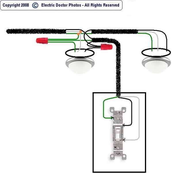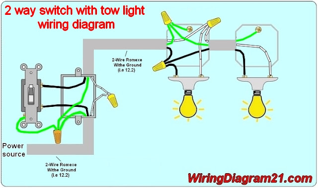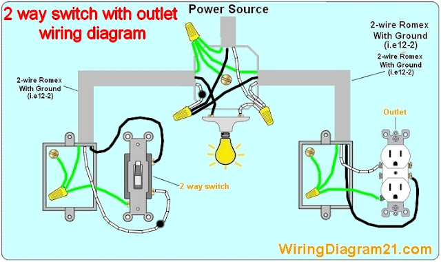

All of these components can be seen in detail in an Australian light switch wiring diagram, which can help to make installing and maintaining electrical systems much easier. In terms of the colour coding of wires, red wires are usually for primary power, black wires for secondary power, green or bare wires for ground, blue wires for switched power, yellow wires for switched and/or live feed and white wires for neutral. A fuse is used to protect the circuit from overcurrent and overvoltage, while a capacitor is used to hold the charge and discharges it when required. For example, a relay is an electrical switch which is operated by a low voltage signal and can be used to control a large amount of current that can’t be handled directly by the switch. When it comes to the various components of an electrical circuit, such as relays, switches, fuses and more, wiring diagrams can provide invaluable assistance in understanding the workings of an electrical circuit. Various Types of Electrical Components Used in Wiring Diagrams This red wire only needs to be connected if you’re controlling two light fixtures - or if you’re using a dimmer switch for multiple lights. Double-pole switches will also typically have two screws on either side but with the additional red wire connected to a third screw at the bottom. This allows the switch to be used to switch on and off the power. Single-pole switches will typically have two screws on either side, with the bottom screw being connected to the black wire (power source) and the top screw connected to the white wire (neutral).

This type of switch is usually used when two adjacent light fixtures need to be controlled by one switch. A single-pole switch is designed to control one light fixture, while a double-pole switch is designed to control two separate light fixtures. When it comes to light switches in Australia, there are two main types - single-pole switches and double-pole switches. In Australia, red, blue and yellow wires are also used it indicate specific circuits.
#2 light switch wiring generator#
Power lines that start from a battery, plug or generator will typically have three core parts - a black line for power, a white line for neutral and a green line for ground. The basic structure of wiring diagrams typically consists of the power line source, the load, and then the connections between the two. This makes for an extremely efficient way of diagnosing and repairing any issues with a complex wiring system. It helps electricians identify the components in the circuit, as well as works to match up the available wires.

It shows how each part of the system works together to create a fully functional electrical circuit. What is a Wiring Diagram and How do They Work?Ī wiring diagram is a visual representation of an electric circuit. To ensure you follow the necessary regulations and keep your electric system running safely, it’s always best to familiarise yourself with the guidelines provided in the local building code. While the principles behind wiring are the same for individuals of all electrical levels, knowing the Australian wiring standards can still be tricky. Installing a light switch is often one of the most common and simple tasks for many electricians. This article provides a quick introduction to how wiring diagrams are used in Australia, along with some helpful tips to get you started. The Australian light switch wiring diagram is a useful tool when it comes to wire installation, as they allow you to easily identify the different types of light switches and their installation procedures. Understanding Wiring Diagrams For Light Switches In Australia


 0 kommentar(er)
